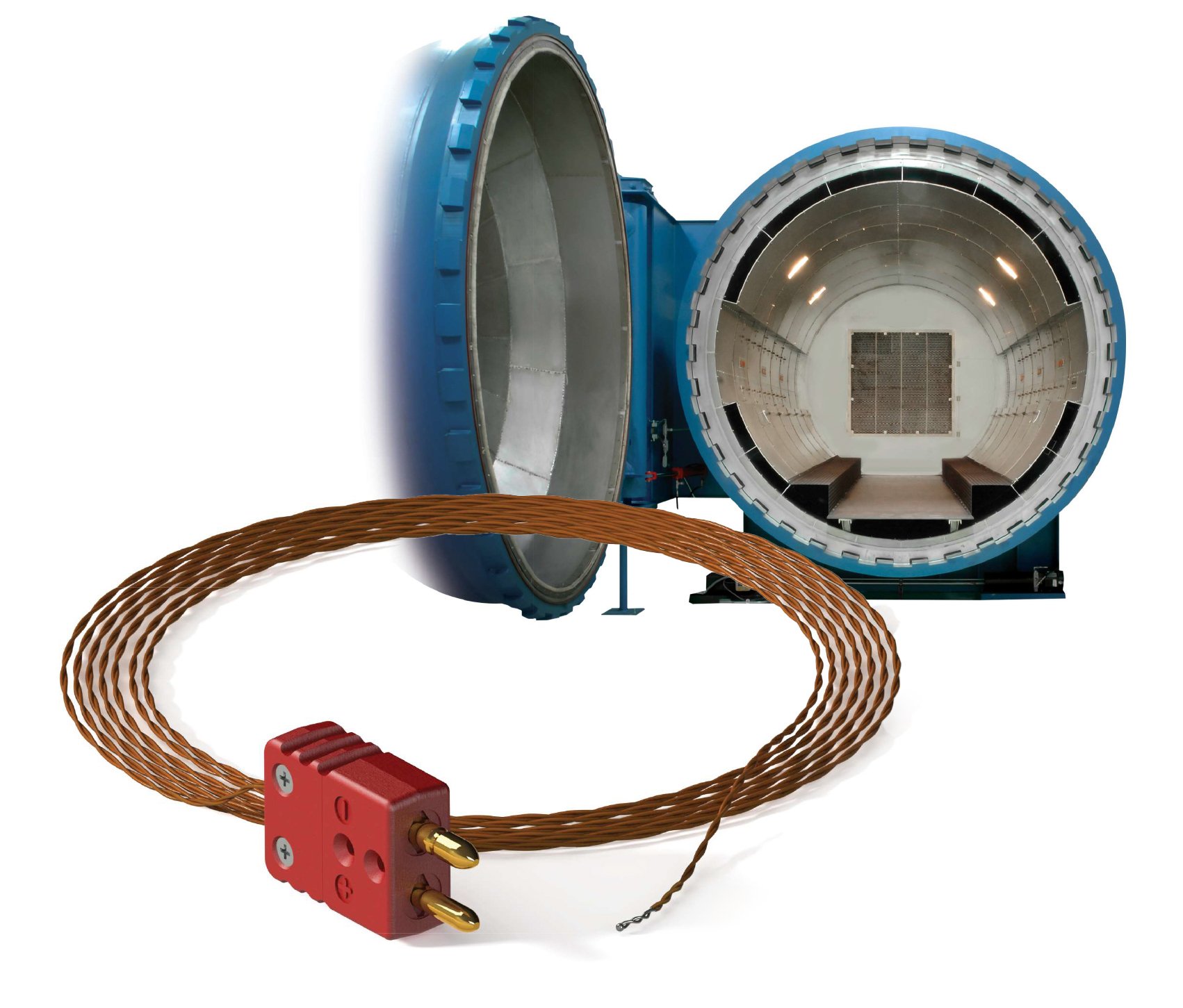
Thermocouples are the most frequently used temperature sensor in the heat process and control industries, with the majority of applications falling within the range of 500 to 1500°C. There are newer technologies like fiber optic distributed temperature sensing systems, wireless sensing, laser IR temperature sensors, IR Cameras, and thermal noise thermometers. However, most exhibit high error, packaging problems, high price or a combination of these issues.
Bottom line: A thermocouple sensor is still the most cost effective and efficient solution for high-temperature harsh environment sensing – even with some drawbacks.
An argument in favor of thermocouple technology would be much easier to make if the calibration of the thermocouples never changed. However, the fact is that thermocouple calibration does change. The magnitude and the direction of this change are dependent on temperature, time, environment conditions and other factors. (See Table 1.)
Table 1: Factors Affecting Calibration of Thermocouples and Thermocouple Systems
| Circuitry Problems | Metallurgical Changes of the Thermoelement | Environmental Consideration in Thermocouple System Designs |
|
|
|
Source: Thermocouple Systems Technology and Application for Gas Turbines
Since the 1990’s there has not been any significant breakthrough in thermocouple technology. Many users wanted a more stable thermocouple cable and something that would have a much longer service life both in repeatability of results and reuse.
In the last decade, many attempted to solve issues like conductor oxidation and contamination, but the approach was very singular, focusing only on one aspect of thermocouple rather than the complete design. Some of this singular research seemed promising, but ended up being unreliable in other ways.
It wasn’t until around 2009 when research by Dr. Michele Scervini and Professor Cathie Rae, both at the Department of Materials Science and Metallurgy at the University of Cambridge, started looking at, not just the conductors chemical structure, but also the behavior in temperature.
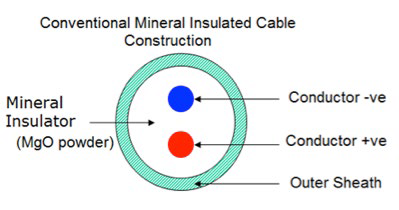
Dr. Scervini began looking at the interaction of all components to solve the current shortcomings of mineral insulated metal sheath (MIMS) thermocouples. The research covered the effect of each component within the construction of common metal sheathed thermocouple in depth (see Figure 1). Researchers looked at conductors, mineral oxide insulators and metal sheath materials. Cambridge researchers carefully studied each piece of the construction and how they interact with each other to achieve the ultimate thermocouple design.
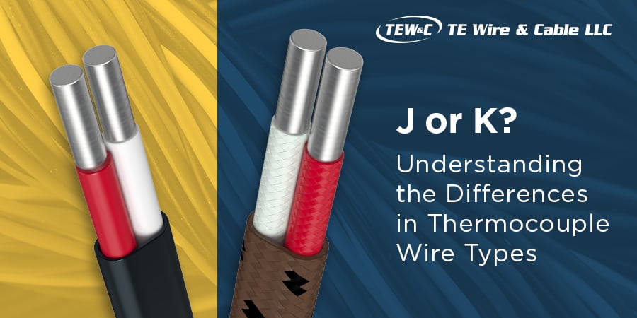
Both type K and type N thermocouple combinations in operational conditions during extended and/or high-temperature conditions are shown to have a limited life operation. Studies at Cambridge have shown increased levels of elements such as Mn and Cr in used base-metal thermocouple conductors. These studies also revealed that the levels of these elements had penetrated deep into the thermocouple conductor’s surface after only a few hours of operational use.

Figure 1: Conventional construction design for Mineral Insulated Cable
The source of these contaminants and other chemical elements has been identified as being 1) the other thermocouple conductor and 2) the outer sheathing of the mineral insulated thermocouple cable.
Further tests conducted at Cambridge have shown the major source in terms of both volume and material that causes higher rates of drift is the mineral insulated thermocouple’s outer sheathing. As would be expected, the higher the temperature of operation, the greater the rates of these changes. This varying amount of changes down the thermocouple conductor’s length results in an increase in the heterogeneous nature of the base metal thermocouple conductors, thereby having a significant contribution to the observed rate of drift.
Dr. Scervini noted that the metallurgical phenomena involved in drift can be distinguished in two ways:
- surface modifications, which are related to changes in the thermoelements because of interactions between the thermoelements and the environment around the thermoelements,
- bulk modifications, which are related to changes in the volume of the thermoelements.
The surface modifications are reported as the following:
- oxidation (bare wire configurations),
- depletion of elements from the thermoelements (bare wire/MIMS configuration)
- contamination from the environment (bare wire/MIMS configuration),
- interaction with the insulator (MIMS configuration),
- interaction with the sheath (MIMS configuration)
The bulk modifications include the following phenomena:
- phase transformations
- short/long range ordering transformations
- grain growth
- residual strain and dislocations annihilation
- recrystallization
This breakthrough in understanding that temperature and time activates the process resulted in them developing a new thermocouple design with a second sheath inside the first. (See Figure 2.) This second sheath works as a filter soaking up the manganese from the outer sheath and prevents the manganese element from migrating into the thermocouple wires.
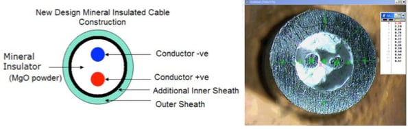
Figure 2: New construction design for Mineral Insulated Cable (left), photo of new construction sample (right)
This vastly improves the accuracy of the thermocouple, while also greatly improving drift characteristics of type K and type N thermocouples. This new technology is ideal for high temperature applications. The new design also lasts longer, improving maintenance turnaround times. (See Figures 3 & 4.)
%20Calibaration%20Results.png?width=595&height=294&name=Figure%203%20-%20Low%20Drift%20Cable%20(LDC)%20Calibaration%20Results.png)
Figure 3: Low Drift Cable (LDC) Calibration results on Cycle 1-91 (each thermal cycle = 400 minutes)
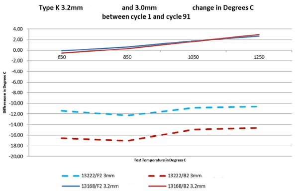
Figure 4: Type K Performance Comparison – New Low Drift Type K design MI (3.2mm) v. Old design MI (3.0mm) Cable
The potential applications for this new LDC technology are endless, especially in the aviation/aerospace and heat treatment industries. This technology will help propel a new portfolio of high accuracy wire, high temperature wire and sensors for increasingly harsh environments.
What’s next? Further research, partnerships and cooperation with forward thinking customers to promote the benefits of a more accurate, low drift, longer life thermocouple sensing technology.
Interested in learning more? Feel free to request the new Low Drift Thermocouple Cable Application Brief. You will automatically be signed up to receive updates. If you have further questions or an immediate need, please contact me at v.fedorchak@tewire.com.
Learn More: